|
Micro-Trak 300 - V1.3 APRS Tracker This page describes building a Micro-Trak V1.3 kit and APRS tracker for high altitude balloon use. Tony required a tracker for future SABLE flights after SABLE-2 was unable to be found last summer and purchased a Lassen iQ GPS Receiver, Embedded Antenna and Byonics Micro-Trak 300 for me to build him a new one with. |
|
|
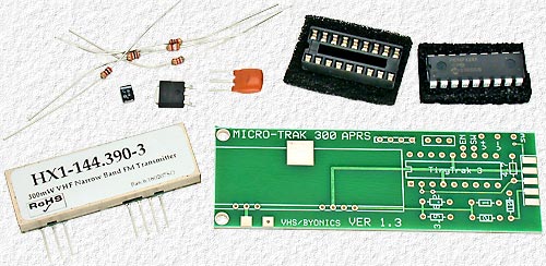 |
The Byonics Micro-Trak 300 kit only has a few components and is very easy to build. As usual, I did some things a little different then in the instructions and made a few mod's s I felt were important or worthwhile to improve performance. The first thing I did was set the I.C. socket aside for use with something else. |
|
|
Sockets are ok for experimenting or when problems are expected that may require replacing a chip, but for projects like this, where reliability is so important, leave nothing to chance and don't use a socket. It's unlikely a TinyTrak chip in something like a Micro-Trak will ever need to be replaced, if one is even just a little bit careful, and if one does, it's simpler and much easier then having to deal with the problems a socket can cause, especially as it gets older. Below - The board wasn't designed to have an antenna connector installed, but a SMA connector was required for the antenna and one was able to be installed as shown. But this is no longer a problem with newer V1.4 boards that are designed for a SMA connector which now comes with the newer board. Hot Glue was used on both sides of the board to bond the small connector and provide strength when making connections. Hot glue was also used to embed the red & black leads supplying power to the board to provide strain relief and keep the leads from flexing and breaking at the point where they were soldered. |
||
|
Micro-Trak Bottom View
|
||
|
Micro-Trak Top View |
||
Some regulators, like the KF50, require an output, rather then input, capacitor for stability so, to avoid confusion and problems, just remember that it never hurts and is always best to use both, an input and an output capacitor, on all 3 terminal regulators.
|
||
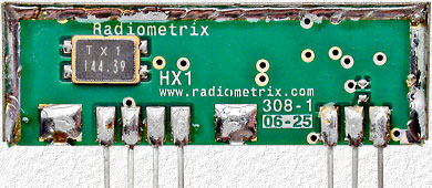 |
I've been waiting to get my hands on one of these intriguing little modules and the chance to check it out for whatever else it may be useful for. The Data Sheet says it's for long range data transfer use for up to 10km, but it's SABLE-3 APRS transmissions were received over 600 km away which proves those saying 300mW is not enough power to be useful for APRS -- are wrong. |
||||||||||||||||||||||
|
|||||||||||||||||||||||
|
The HX1 module is very temperature dependent. When transmitting both modem tones (using the TinyTrak configuration program) the center frequency was ≈500Hz high at room temperature (≈70°F). (Both tones were used as the center frequency is actually different for each tone as explained later.) The module temperature was then increased by transmitting continuously until the frequency was correct at ≈95°F. 70°-95° is likely the most common temperature range that will be encountered for most 'down-to-earth' uses and 500Hz accuracy isn't all that bad, but when placed in a freezer at ≈0°F (-18°C) the frequency ended up being 1.2 kHz high which isn't good considering this tracker is for high altitude balloon use and may experience even lower temperatures. On BEAR-3, our first altitude record attempt and with only the tiny amount of heat dissipated by the GPS and Micro-Trak to keep things warm, everything was found covered with ice crystals when the insulated payload box was opened. It's hard to know how cold things got, but we were probably lucky the trackers transmissions were all able to be decoded with how far the frequency was likely off. With more time, it would have been interesting to have plotted the transmit frequency vs. temperature before the flight and to have used a receiver with a deviation meter to know just how cold things got and how high the transmit frequency ended up being. Accurate deviation measurements were hard to make with the carrier frequency constantly changing as measurements were made, but close enough to determine why things were the way they were. The TXD pin is a DC coupled CMOS compatible input and with the pin biased at 2.5V the carrier frequency was close to 144.390 MHz as expected (depending on temperature, of course). With the pin at 0 and 5V I also expected the frequency to shift ± ≈2.5 kHz, but it actually shifted −3.2 kHz and +2.2 kHz and accounts for why the demodulated tone waveforms are distorted like they are and why the center frequency is ≈100Hz higher for the 2200Hz tone then for the 1200Hz tone. From the data sheet information, the HX1 is obviously designed for digital, rather then analog, modulation and with digital modulation the non-linear deviation would make no difference, other then making the center frequency appear ≈600Hz lower then what it is with the TXD pin at 2.5V which would make it almost correct at room temperature. |
|||||||||||||||||||||||
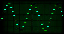 The 1200 Hz tone waveform from the TinyTrak 4-bit D/A converter. |
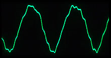 The 1200 Hz tone waveform after low-pass filtering in the transmitter. |
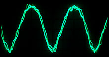 The received waveform is distorted with the upper half more rounded then the lower half from the unequal deviation resulting from each half. |
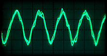 2200Hz tone deviation is less then for the 1200Hz tone due to the transmitters low-pass filter which starts at ≈1.8 kHz. |
| Confused and wondering what all of this really means? It simply means that the Micro-Trak is a quick, simple and easy way to build a tracker that's good for most applications, even for tracking high altitude balloons in many cases, but to expect problems, especially in cold situations, and that there are better transmitters to use. A Balloon_Sked entry at yahoo groups once questioned why a tracker had failed above 60K ft. (thus proving the GPS was ok for such altitudes), but started working again after returning much lower. I first guessed that the batteries likely froze from too little insulation, but upon learning it was a Micro-Trak it's much more likely that the cold had simply caused the transmitter to drift too far off frequency to allow the transmitted data to be received and decoded. | |
|
Some may be able to program a TinyTrak using a RS-232 port directly, but I have yet to find a PC or laptop RS-232 serial port that will accept logic level data and TinyTrak's use of inverted logic level data has only caused problems and confusion for myself and all those I've helped. TinyTrak3 is a big improvement over previous versions with being made to work with either normal, or inverted, logic level GPS data, but it would have been nice to see the same done for programming data to save having to provide extra circuitry (inverters) following a RS-232 or USB interface chip in order to accommodate TinyTrak's inverted data. Using inverted data to save having to use a RS-232 interface chip is fine for personal project, but there are standards for a reason and they should be followed for things being marketed to prevent confusion and problems. As for why the Micro-Trak idle current is listed as 39.2 to 41.5 ma. in the HX1 transmitter section above, it's because the four TinyTrak D/A output pins are left in 1 of 16 different random states after each transmission which results in 16 different levels of standby current. Not a big deal, but it would have been nice to have them always left in a high state to reduce the standby current a few ma. and make it consistent for easier measurements. |
|
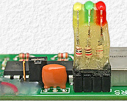
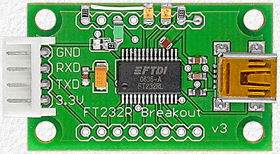
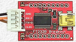
RS-232 serial port interface cables were used in the past for devices with a logic level interface, but I now use USB serial ports as I find them much simpler to use, my lap top has no RS-232 port and USB ports are often able to power what they
This is not unlike installing facility maintenance software on a business's computer systems but only on a much smaller scale. The description appearing in the list of connected USB devices on a PC can also be modified and was changed to "FT232R TinyTrak Interface" to indicate that this board was modified for inverted data and TinyTrak use. A Red Tx Data and Green Rx Data & Power LED was also added and the board was modified to supply 5V, rather then 3.3V, via the 4-pin connector.
|
|
|
|
|
|
NEXT SEE: |
This Micro-Trak with a Trimble Lassen iQ GPS as used for SABLE-3 |
| This Micro-Trak with a Trimble Lassen iQ GPS as used for BEAR-4 | |
| A similar V1.4 Micro-Trak with a Trimble Lassen iQ GPS was used for BEAR-3 | |
 are used with which saves having to deal with a another power source and cable. And a
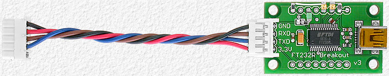
The SABLE Tracker Wiring & Modification Details PDF has wiring & further Micro-Trak, GPS & USB Board Details.
| To BEAR Home Page |