Tracksoar V1.1 TrackerTracksoar High Altitude Balloon Tracker from
www.tracksoar.com I needed some new trackers and thought about making some from scratch using SMD devices to keep them small and light, but this would mean first having to learn Eagle CAD in order to design the PCB and having to make a reflow oven so I decided to simply buy a couple of Tracksoar trackers from Mike at tracksoar.com that had already done that. |
|
||
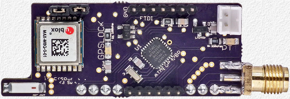
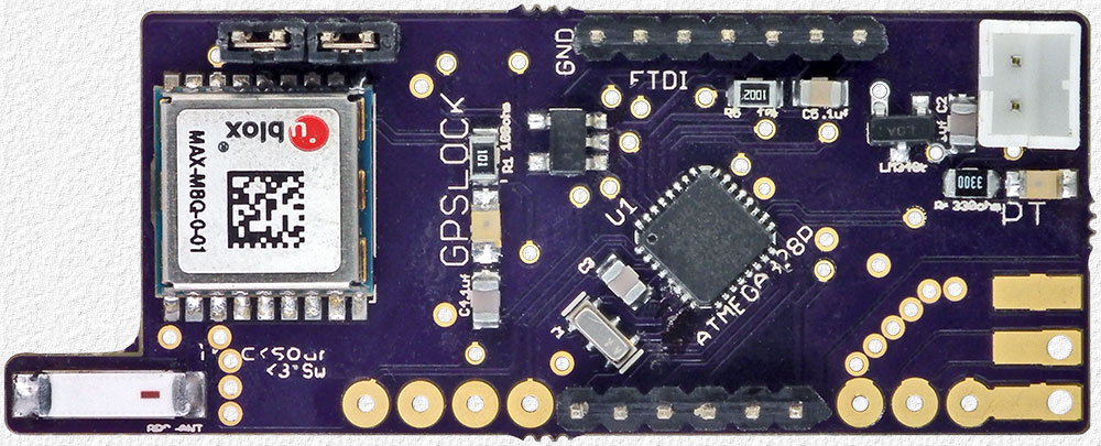 Above - Top Side of the Tracksoar V1.1 tracker board which has an ATMEG328P processor, ublox GPS, BMP180 Pressure & Temperature Sensor and a SHT21 Humidity Sensor. The Tracksoar firmware is the free Trackuino APRS Tracker Software with the libraries and changes needed for the BMP180 & SHT21 sensors added. |
|||
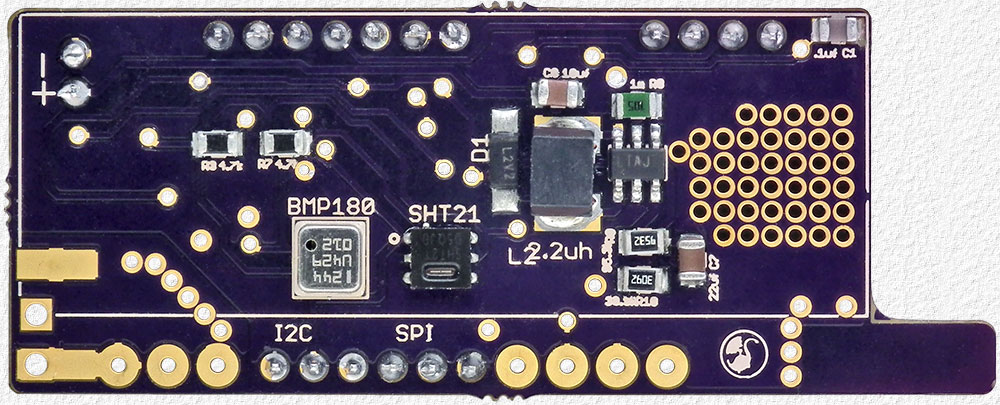 Above - Bottom Side of the board with the BMP180 & SHT21 sensors. The Tracksoar requires a supply voltage of between 1.5 to 5.0 volts and is supplied with a very nice battery box for 2 AA cells which has a slid on cover held in place with a small screw to ensure the cells will not pop out upon a hard landing or whatever. The tracker has a Step-Up DC/DC converter that provides regulated 5V for the processor and a linear regulator that provides 3.3V for the GPS and BMP180 & SHT21 sensors. |
|||
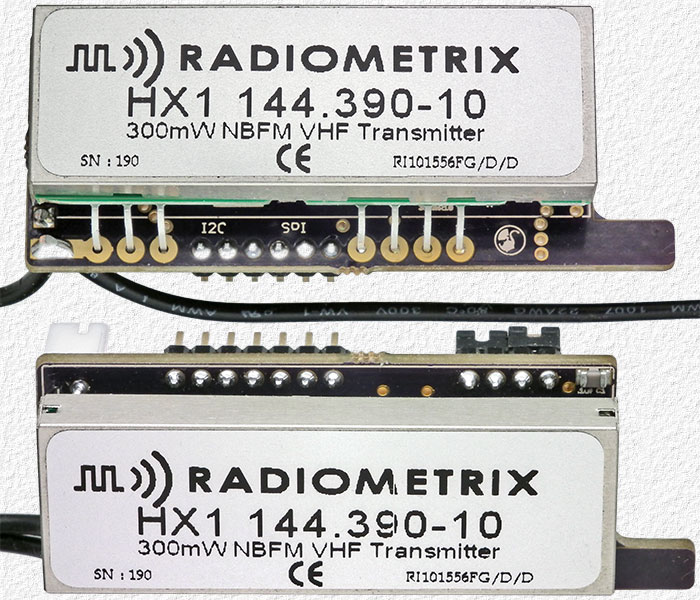 |
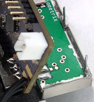
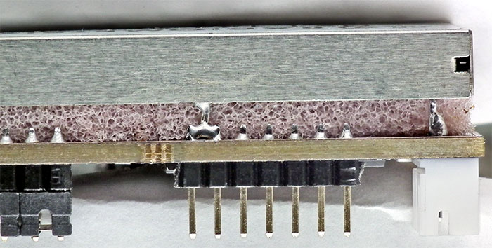
Left - The Tracksoar is designed for use with a Radiometrix transmitter module, but any suitable transmitter can be used. The Micro-Trak 300 tracker I wrote about in 2007 used the same HX1 module and you can read more about the module there and what I had to say about it at that time. I wasn't too impressed with the module as it wasn't very temperature stable, but keep in mind that was a -3 version, 9 years ago, and my Tracksoar has a -10 version which is likely much better and I'll be checking out and reporting on as soon as I have time. Note: With a Radiometrix module one needs to ensure that it remains spaced a short distance off the tracker board to prevent it shorting and having the tracker fail which could easily happen as the top edge of the transmitters metal enclosure lines up almost perfectly with the soldered header pins on the tracker board as seen in the second (lower) image. The trackers come with some pink foam between the two units to keep them separated, but foam can be compressed which could result in a short if the tracker is packed too tightly in a payload or from the force of impact when landing and I believe my method that follows is much better. |
||
|
|||
 |
The pink foam that came with the tracker and can be seem is no longer needed. I simply forgot to remove it before adding the lead standoffs and it was removed later after this photo was taken. | ||
 |
|||
|
One of the things I like about the Tracksoar is that it's Arduino based and I'll be able to add some additional features that I would like to have. It's hard to say how I'll make out trying to add the features I would like to have as, although I've been working with and designing hardware circuits for >50 years, I have limited software experience, only written a few PIC programs using BASIC the past few years and only began working with Arduinos several weeks ago. I have two Tracksoar trackers and installed a SMA connector on the one shown above to allow a SMA dummy load to be used and not have to deal with a wire antenna strung across my desk while developing and testing firmware changes. June 14 - Firmware Update. I've been using Arduino IDE v1.69 while learning how to program an Arduino, but Arduino IDE v1.6.5 needs to be used with the current Tracksoar v1.1 firmware and to save having to deal with using two different Arduino IDE versions I decided to start by trying to update the Tracksoar firmware and I'm now able to use the latest Arduino IDE v1.69 with the firmware. Updating the firmware took much longer than I planned however, as early on I somehow managed to wipe out the ATMEG328P bootloader and first had to learn all about boot loaders, ATMEG328P fuses and how to install a new boot loader. One thing learned while doing this, and something to note is that, from the factory, the ATMEG328P lock byte fuses are not set to protect the boot loader from being over written when one uploads new firmware, like one must do after entering their call sign and editing the configuration file. In the end, I replaced the 1024 byte factory boot loader with a 512 byte Uno Optiboot 16 MHz loader using the procedure found at http://www.gammon.com.au/bootloader which also correctly programs the lock byte fuses. The best part was learning that I didn't need to buy a special programmer and could simply use an Arduino UNO. I'm not sure how much of a problem overwriting an unprotected boot loader is and if the factory boot loader in my other Tracksoar will also be overwritten when I try to program it with the updated Tracksoar firmware, but will report back here with what I find once that's done. June 30 - I've added some new features to the firmware that I missed having on other trackers or thought would be nice to have. The 1st is one that changes the APRS path based on the trackers altitude. In addition to a WIDE2-1 or NO PATH, one can now chose to use a WIDE2-1 path when on and near the ground and NO PATH above whatever altitude is chosen and entered in the configuration file. The 2nd adds the number of GPS Satellites In View and the GPS HDOP values to the other information being reported. The 3rd is a feature that has the tracker calculate and report the ascent rate. Following a launch it's nice to check and see how close the actual ascent rate is to what one aimed for and this feature saves having to have a way to view the aprs.fi raw data log and having to repeatedly manually calculate the ascent rate. The ascent rate can also be used to help determine when a balloon is about to burst and following burst it's always interesting to see how fast a payload end ups falling before it reaches atmosphere dense enough to start slowing down the descent. Reporting additional information increases the message length and transmission time which increases the chance of a transmission error so I've made it possible in the configuration file to select which data one wants sent in each transmission. When I find time I also plan to try compressing the data and adding an option as to whether, or not, send compressed data. It doesn't shorten the message length much, but the reported internal temperature (Ti) was changed from 2 decimal places to 1 decimal place as the second decimal place is always 0 and simply of no use. The 4th new feature is one for those that like to try to beat their own altitude record or that of others. The first few transmissions after a balloon bursts are often lost due to PBC (Post Burst Chaos) and this feature keeps track of the maximum altitude reached, determines when the balloon bursts and then adds this information to the transmitted comment. If the altitude is only checked at the time of each transmission, the burst altitude could actually be a fair bit higher than at the time of either transmission, just before or after, the burst so the altitude is checked every 10 sec's which, at an ascent rate of 1000 ft/min, would make the reported burst altitude accurate to within 83 ft which is better than the accuracy of GPS altitude data. The processor is normally asleep between transmissions, to conserve power and extend battery life, and waking the processor up to check the altitude more often will affect battery life and I'll determine how much a bit later. As for determining when a balloon bursts, this is done by checking for an altitude loss of > 500 ft which should be enough to prevent any altitude data accuracy fluctuations from being reported as a burst, but this value can be easily changed if it's not. The PTT LED, although it becomes bright around the time of each transmission, actually indicates when the processor is awake and busy processing instructions which is why it's dimly lit between transmissions when the processor is only awake very briefly to check if it's time for another transmission each time GPS data is received and then brightens when it's time to make a transmission and the processor remains awake for much longer. After adding the 4th new feature this LED also becomes bright every 10 sec's when the processor is kept awake while checking the altitude and for a burst which makes it hard to know when a transmission actually occurs so a configuration setting was added that allows the PTT LED to be used as either a processor activity indicator or as a real PTT indicator that's only on during a transmission. While testing the added features, a problem was discovered with the Trackuino slotted transmission option. The slotted transmissions appeared ok at first (although they occurred 1 sec later than they should), but over time the transmissions occurred increasingly later which made this option useless. The problem was that the Trackuino firmware didn't account for the time the processor spent processing instructions which varies a bit each transmission period due to the varying data involved and my solution was to simply recalculate a new start time after each transmission and then subtract 1 sec to have the transmissions occur on time. The Trackuino firmware checks for several problems, like a missing or failed sensor, which are only reported via the debug feature, so I've added an alarm feature to notify one of a detected problem at other times that rapidly flashes the PTT LED on and off. Please don't email and ask for a copy of my firmware as (1) I already get enough email and (2) I've decided it would be best to only share it with Mike (at tracksoar) that also plans to add some additional features so he can merge my changes with his to prevent having two different Tracksoar firmware versions with different features being used rather than a single version with all of the features. July 22 - I'm working on two more features, but these will require additional hardware that's connected to 3 of the header pins. One feature provides for 2 additional temperature sensors for perhaps monitoring the external temperature (outside the tracker enclosure) and battery temperature. The firmware is written for up to 2 DS18S20 1-wire temperature sensors, but many more could be easily accommodated with a minor firmware change. The 2nd feature adds another another 1-wire device, a DS2413 two channel I/O chip which can be used to provide 2 digital inputs, 2 outputs or 1 of each although the firmware is currently written for 2 outputs controlled by the trackers altitude. The idea behind this feature is something I've wanted to try many times which is to keep the parachute stored inside the payload container until after the balloon bursts and the payload has fallen to several thousand feet of the ground to keep the payload from being blown much further away than it would otherwise be on a windy day. I plan to design an add-on board for these 2 features although the header pin connections will all likely be required for the future add-on data logger board being developed by Mike (at tracksoar) which means both likely won't be able to be used at the same time (unless firmware can be used to share one of the pins). August 6 - I've done some rough power supply measurements (rough measurements as the current constantly fluctuates making accurate measurements difficult). August 27 - Our BEAR-21 flight used 2 Tracksoar trackers with my modified firmware and everything worked fine except for the reported burst altitude that was wrong due to a data formatting error which was corrected a few days later. And since it was a formatting, rather than a calculation, error the correct maximum altitude reached was still able to be easily determined. A RTrak tracker was also used and the 3 trackers were set to transmit once a minute and time slotted 20 sec's apart. Burst occurred mid way between 2 of the transmissions and the new Tracksoar feature that keeps track of the maximum altitude reached (Burst Altitude) did its job and showed the burst altitude was several hundred feet higher than either of the 2 transmissions just before and after burst. Several hundred feet isn't much, but this was a test flight for the new firmware with transmissions only 20 sec's apart and the burst altitude feature would obviously be more useful using a more typical once a minute or slower transmission rate. November 3 - I've further refined the firmware and have been working on a couple of new features which would have been useful in the past and especially on our last flight which consisted of 2 payloads with 2 trackers installed in-line between the parachute and first payload and a 3rd tracker tied on below the second payload. During PBC (post burst chaos) the line between the 2 payloads was somehow cut and we ended up having to track and recover 2 separate payloads. One landed a short distance from a road in a gravel pit and the second landed several miles away in a tree. The payload on the ground was easy to spot, but the one in a tree was about 70 feet up and only visible from one location on the ground that was found by chance when the recovery person just happened to look up at the exact time needed after repeatedly searching the area around the tree for several hours. Anyway, this reminded me of a tracker feature that I've wanted for some time which is a switched output, configured to activate during descent shortly before landing to use with an audible and/or visual device to help locate a hard to see payload. Some simply use an audible device that's on the entire flight, but that requires using a larger and heavier battery than necessary plus I hate hearing the very annoying high pitched beeping sound of a sonalert alarm every time I hear one in an otherwise good you-tube HAB flight launch video. Anyway, check back from time to time for what I am working on which, at the moment, is adding a DS2413 two channel I/O chip to the piggy-back board to allow connecting additional temperature sensors that I talked about working on above on July 22. One of the firmware refinements made after our last flight was the shortening of the transmitted packet by removing all of the unnecessary '=' characters. VE6ATV-11>APRS:/225945h5355.57N/11239.11WO264/003/A=82668/Sats=12/HDOP=0.76/AR=−6043/Pa=2772/Rh=5.96/Ti=−3.7 BURST@88850ft Tracksoar v1.3 which would now appear as: VE6ATV-11>APRS:/225945h5355.57N/11239.11WO264/003/A=82668/AR−6043/Sats12/HDOP0.76/Pa2772/Rh5.96/Ti−3.7 B@88850ft Tracksoar v1.4 Not a huge difference in length by eliminating all the '=' signs and shortening BURST to simply 'B' and undecided about keeping the shortened version until I get some feedback from those that help track and recover our BEAR payloads. I've also moved the position of the Ascent Rate to after the Altitude as these values are the ones most are most interested in and grouping them together makes it a bit easier and faster to spot the Ascent Rate. And using the trackers for an actual flight identified something I hadn't noticed while testing the firmware which was that when the trackers were powered on for the flight with the PTT LED configured as a PTT indicator that there was no way of knowing if the trackers were actually receiving power, or not, until the GPS got lock and the GPS LED started to flash so that's now been fixed by having the PTT LED come on when power is applied until lock is achieved and the GPS LED begins flashing. April 25 - 2017 - A small problem was found shortly after my last report. I then took a break for Christmas and to work on a few other projects, before working on the firmware again this past week and it now appears to be ready to use for a flight. The software problem had me take a good look at transmission timing and when Time Slotted Transmissions occur for different Transmit Rates and Slot Times. When Time Slotted Transmissions are Disabled (by entering -1 for the APRS_SLOT time) the first transmission occurs when the tracker is powered on and then transmissions will continue at the Transmit Rate (determined by the APRS_PERIOD). However, the time from the start of one transmission to the start of the next is NOT exactly the same as the APRS_PERIOD as it takes time to process the software instructions involved with updating the time for the next transmission so the actual duration is a few ms longer and, after an hour with an APRS_PERIOD of 60 seconds, transmissions will occur ≈ 8½ sec's later than they did the hour before. Having a few ms added to the duration ends up being a good thing (and one may even want to consider adding 1 or 2 sec's more to periods, like a 60 sec period, that would otherwise have transmissions occur at the same time (in sec's) from the start of each minute) as it prevents ending up always transmitting at exactly the same time each minute and as a station that may be using time slotted or some other type of transmissions that always occur at the same time each minute. When Time Slotted Transmissions are Enabled (by entering an APRS_SLOT time (in sec's), is used for the, help prevent multiple trackers in a special event from sending packets at the same time. They are also useful when needing to know exactly when to listen for a transmission, like when doing a grid search for a lost payload in hope of getting close enough to hear a transmission and trying to determine which of the transmissions being heard may be from the lost payload and which are from elsewhere. Knowing exactly when Time Slotted Transmissions should occur is pretty easy for a period of 30 or 60 sec's, but it becomes more complicated for other periods and I wanted to make sure my code worked as it should, but there doesn't appear to be any detailed information about Time Slotted Transmissions on the web other than what's found in several of the TinyTrak manuals which I've summarized below. If "Time Slotting" is enabled, the "Transmit Offset" setting sets the time from the start of the hour that a transmission will occur. After that, transmissions will continue at the "Transmit rate" until re-syncing at the next start of the hour. The "Transmit Offset" value must be less than the "Transmit Rate". TinyTrak will transmit at the Transmit Rate, even if it has not yet synced and will only synchronize with the GPS time at the start of the hour, so there may be a delay of up to an hour before it begins transmitting in its assigned slot. It is not important to sync every minute, because TinyTrak3 timing doesn’t drift very much over an hour. If the Transmit Rate evenly divides into 600 seconds, TinyTrak will synchronize at every 10 minutes. One must obviously be careful when choosing a Transmit Rate with it taking up to an hour for a tracker to begin transmitting in its assigned slot for some periods. Anyway, it would take a long time to confirm when the Tracksoar transmissions would exactly occur for all the different Transmit Rates I wanted to check using the Tracksoar and having to wait at least 15 minutes each time while the times were logged so I made a MS Excel spreadsheet that uses the same formula that Tracksoar does to calculate transmission times which I've found quite useful. Download Tracksoar Time Slotted Transmission Times xlsx Note: The Tracksoar calculates it's Time Slotted Transmission times a bit different than the TinyTrak does and re-sync's after each transmission which means that there's no waiting for 10 minutes or for up to an hour for it to re-sync for some rates. More will follow eventually when I have time, like the Tracksoar Power Requirement Spec's and Evaluation of the -10 version Radiometrix Transmitter Module, but now that the firmware appears to be ready for another flight test again I've decided to share it with others directly as well as send a copy to Mike (at Tracksoar) so he can make it available on the Tracksoar web site with the additional features he comes up with and wishes to incorporate. Download Tracksoar Firmware V1.1.2 here or from tracksoar.com (once Mike has a chance to make it available). That's all for now, but check back from time to time for additional information and other features I may be working on. |
|||