 |
Regarding the use of |
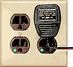
| Wall-warts are NOT the best power source for Comtech ATV receivers and many other devices. Ripple on the receiver supply voltage will cause hum bars in the video because the supply voltage is used, with little additional filtering, as the tuning voltage source for the tuner. | |
|
When using wall-warts, always check the output voltage, under load, to ensure that it is correct. Wall-wart voltage can vary drastically between no load and load conditions. Most are also poorly filtered so it is best to check the voltage with a scope to determine the minimum voltage supplied rather than with a voltmeter which will provide the minimum voltage plus the average of the ripple voltage. If the minimum voltage is not several volts greater than your devices voltage regulator output you should also check the voltage regulator output with a scope to ensure that ripple is not getting past the regulator. If a small amount of ripple is getting past the regulator and no better wall-wart is available, you can sometimes get by with adding an additional filter capacitor to the wall-wart output / regulator input to reduce the ripple and increase the minimum available voltage. A neat way to do this is replace the regulator input filter capacitor with one of a larger value. Wall-warts often have only a 200 - 500 mfd capacitor so adding 2200 mfd, or more, will significantly reduce ripple voltage. Example: For an ATV receiver requiring 12VDC at 240 ma I found a 12 volt, 400 ma wall-wart that with no-load measured 15.4 VDC on my meter. This looked as if it should work, but when the receiver was connected the voltage dropped to 10.6 volts on the meter. A scope showed that the 10.6 volts was really 9.9 volts with 1.4 volts p-p of ripple and that 0.2 volts of ripple was on the 9 volt regulator output. I then found a 12 volt, 500 ma wall-wart that measured 17.5 VDC with no load. Connecting the receiver dropped this voltage to 13.4 volts which the scope showed to be 11.9 volts with 3 volts p-p ripple. The scope confirmed no ripple was at the 9 volt regulator output and that the 11.9 volt minimum voltage was sufficient for the regular. However, since the receiver uses the un-regulated supply voltage, with little additional filtering, for the tuner's tuning voltage source, it could not tolerate the 3 volts of ripple which caused 60 Hz hum bars to roll through the received video picture. To see the difference extra filtering would make, a 1000 ufd capacitor was added to the wall-wart output. This reduced the 3 Vp-p ripple to 1 Vp-p. I ended up using a 2200 ufd capacitor which reduced the ripple to 0.6Vp-p and finally made this wall-wart / receiver combination usable. I do not like un-regulated wall-warts for other than charging batteries, powering properly designed equipment supplied with the appropriate wall-wart or powering properly designed equipment utilizing a switching power supply that can accept a wide supply voltage variance. I qualify equipment with "properly designed" because even though the 13cm ATV receiver employs a switching voltage regulator, the potentially noisy input supply voltage is still used directly as the tuning voltage source. For a few pennies more, a clean regulated tuning voltage source could have been included in the receiver power supply design. |
|
 |
|