|
Dericam H216W & Cybernova CN-WIP880MW |
|
||
|
|||
 |
 |
||
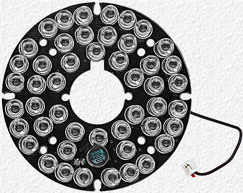
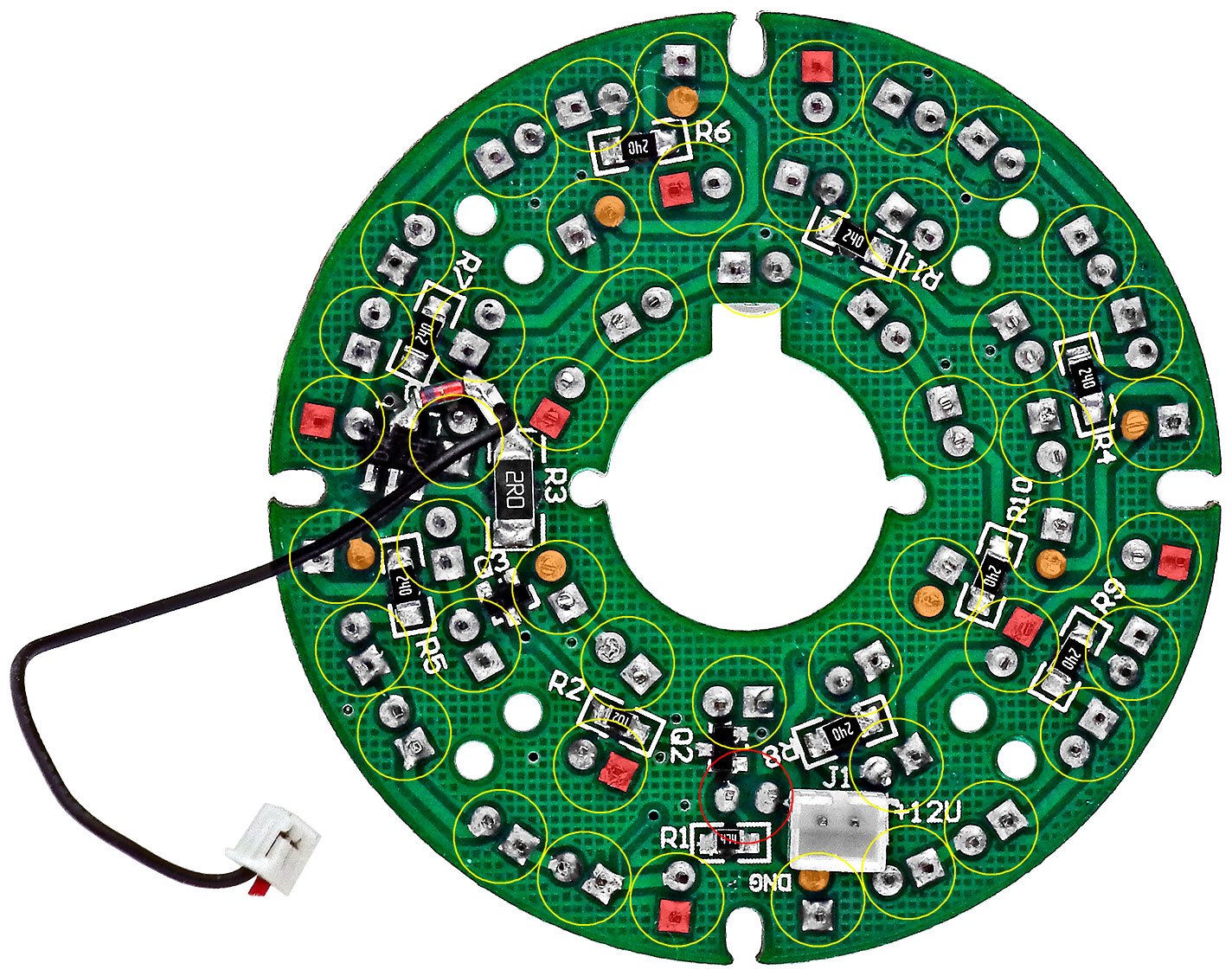
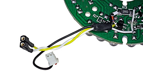
| Above - Front & Rear Views of the camera IR LED Board. The yellow circles overlaid on the rear view indicate the LED locations and the red circle indicates the photocell location on the front side. In addition, the Red colored solder pads are those connected to +12V and the Amber colored pads are those connected to the collector of transistor Q1 on the schematic. Click on the rear view image for a larger image and on this Outdoor_IP_Cam_IR_PoE_Mods.pdf link for a schematic and other information needed. | |||
 |
 |
||
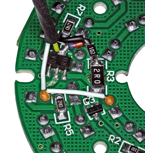 |
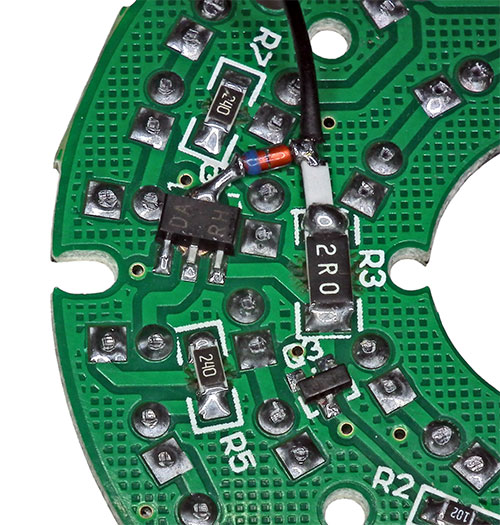
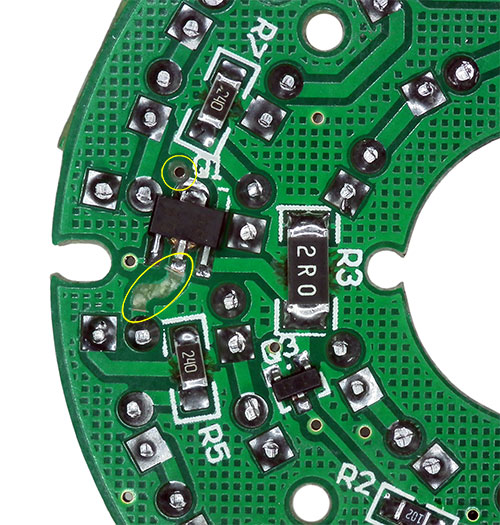
Upper left - Step 1 is to remove diode D1, the 1K resistor in series with diode D1 and the black wire to J15 on the middle camera board. Upper right - The LED assembly consists of 8 strings of 6 LED's in series with a resistor which are then wired together into 2 groups of parallel wired strings with separate connections to the collector of Q1 and step 2 is to remove these 2 connections. One connection is the PCB trace that existed within the yellow oval and the other is the via connection from Q1 to the other side of the PCB within the yellow circle which is easily removed by using a small drill bit to remove the annular copper ring surrounding the via. Left - Step 3 is to reinstall the diode, 1K resistor and black wire removed in step 1. A white horizontal jumper wire was then installed that connects the 2 groups of IR LED's together again and white and yellow wires from an in-line connector socket were added as seen to the left and below.
Left - Step 4 is to cut the trace shown cut within the smaller yellow circle and install the 2 small SMT diodes seen within the larger yellow circle (D2 & D3 in the modified board schematic) from the pad located at the top of the yellow circle to the portion of the cut trace that leads to the via seen at the yellow circle 3 o'clock position. The final steps are to modify the camera cable as noted and seen below and in the Outdoor_IPCam_Mods.pdf. Below - The modified camera cable after the initial IR modification. If doing both, the IR & PoE mod's, please note that the PoE mod. requires a few more changes to be made before heat shrink is applied so you don't end up having to modify the cable twice. |
||
 |
|||
 |
|||
  |
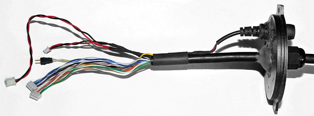
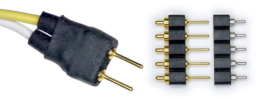
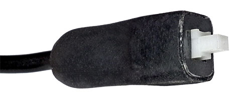
d) The connector on the white & yellow camera cable wires to J4 on the rear camera board was replaced with the plug portion of the small 2 pin inline connector mentioned in step 3. For a small and inexpensive in-line connector you can't beat using heat shrink tubing and pins & sockets cut from longer strips of pin and socket headers.
e) The momentary action reset push-button connected to the white and yellow camera cable wires at the RJ45 connector end of the cable was replaced with a small alternate action On/Off switch salvaged from an old PC that was protected with and encased in heat shrink tubing to make it much like the removed switch in a molded case.
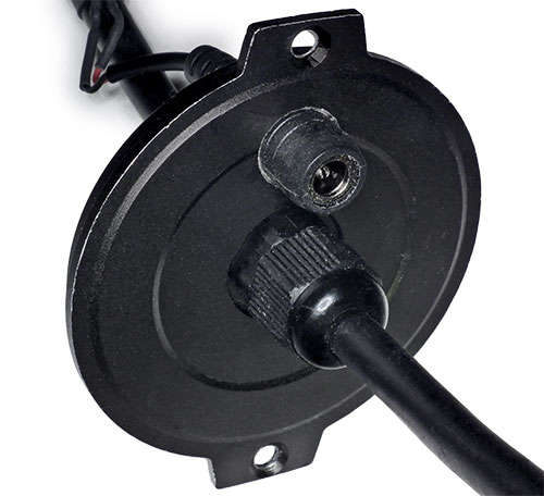
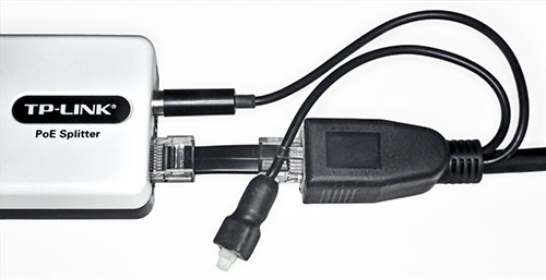
Upper Left - The removed barrel jack press fitted into the enlarged hole where the SMA antenna connector had been. Bottom Left - The modified cable connected to the PoE Splitter that was used until the later PoE Modification was done. |
||
| Amateur Radio Home Page | Next: Outdoor IP Camera PoE Modification |