|
Home Brew Enclosures for Board Cameras |
|
||||||||
|
|||||||||
|
|
|||||||||
Refer to this HomeBrew_Enclosures.PDF for detailed enclosure drawings, dimensions, hole sizes and other details. Note: The HomeBrew_Enclosures.PDF is a copy of the CAD file used to design and keep track of the different enclosures I've made (with a few notes tossed in to help those that may use it to help make their own enclosures). However some pages, like those showing the enclosures I've built, are mainly for me and can be basically ignored. The main page to see is page 4 with the latest designs. The enclosures themselves are all basically the same except for the length and what's actually different from one design to the next is the configuration of the camera each enclosure is for and by camera configuration I mean the different brass spacer length combinations used and board spacing's.
|
|||||||||
|
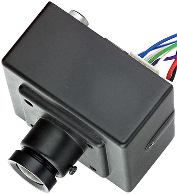
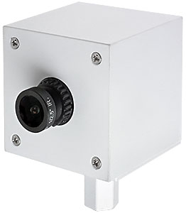
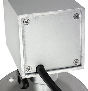
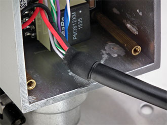
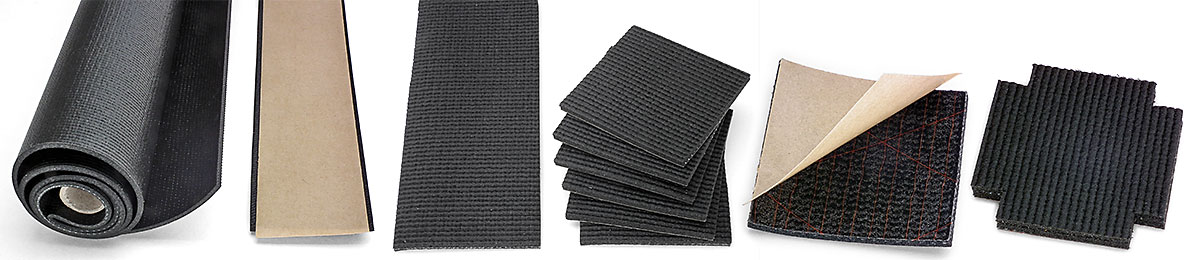
Use Caution when installing a camera module and tightening the 4 front panel screws as the camera board could be damaged. The screws are not connected directly to the IRC filter and once the filter contacts the rubber seal the screws will be applying pressure to the camera board that, in turn, will apply pressure to the IRC filter as it compresses the foam so tighten the screws slowly and each, in turn, a little bit at a time to even out the pressure and give the foam rubber time to compress. When wanting to replace the camera in one of my enclosures with a different one I was concerned that the foam would remain compressed and not provide as good a seal for the new camera whose IRC filter would most likely not end up in the same location and match the first cameras depression exactly, but 24 hours after the first camera was removed its depression had disappeared without a trace of where it had been. The rubber seals don't make an enclosure totally dust and weather proof of course, but cameras installed under an eave or similar area protected from the rain don't need to have anything close to an IP66 rating and I've had no problem with even inexpensive indoor pan-tilt cameras installed outdoors that were only protected by an eave or something similar above them. Two weak areas that remain are the lens threads and rear panel. The lens locking rings I'm now using may be enough to keep moisture from working it's way along the lens threads into the camera, but I don't want to risk this happening as the moisture would be inside the IRC filter along with the image sensor (which is much worse than simply inside the enclosure) and I plan to use either some Teflon tape or silicon grease to seal the threads. As for the small gap between the 4 edges of a rear panel and an enclosure, they will usually end up facing a wall which will prevent water from being blown inside an enclosure, but if concerned one can always use silicon grease, Vaseline or something similar to seal the back panel that's flexible and easy to remove and clean off.
Anyway, I hope this page helps others home brew some enclosures for their board cameras. |
|||||||||
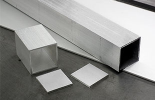
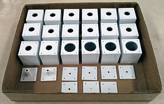
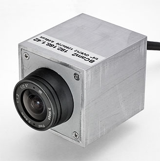 Above - Some of the first enclosures that were made from
a 2 ft. length of regular unfinished tubing that I purchased from a metal supplier before discovering a much longer 9 ft. length of nicely finished anodized tubing in the garage that I had purchased from a scrap metal dealer some years ago for a fraction of what the unfinished tubing cost. Note:
The small hole in the side of the enclosure seen in the first image is the hole that was provided in the first batch of enclosures that provided access to the lens adjustment screw.
Above - Some of the first enclosures that were made from
a 2 ft. length of regular unfinished tubing that I purchased from a metal supplier before discovering a much longer 9 ft. length of nicely finished anodized tubing in the garage that I had purchased from a scrap metal dealer some years ago for a fraction of what the unfinished tubing cost. Note:
The small hole in the side of the enclosure seen in the first image is the hole that was provided in the first batch of enclosures that provided access to the lens adjustment screw.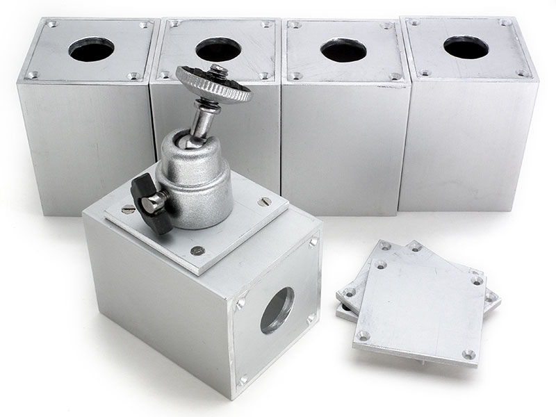
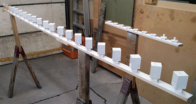
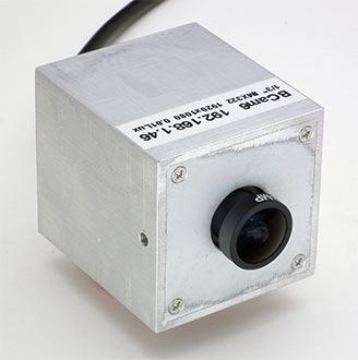
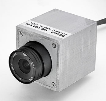
 Above - After making a number of enclosures (and only painting one of the 2nd batch for the image seen earlier) it was time to paint the rest.