|
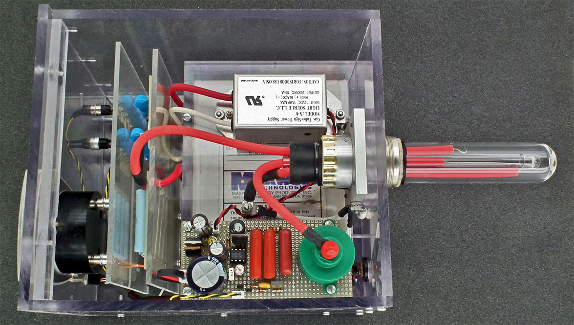
Above - Top View the first time I thought the flash was completed until triggering circuit and 12V to 2000V HV inverter problems were discovered.
|
|
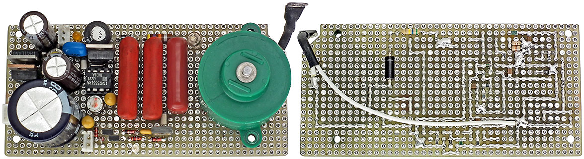
Above - Top & Bottom Views of the Triggering Circuit Board (first version). A heat sink was later added for the HV inverter voltage regulator (in upper left corner),
but the largest heat sink that would fit was marginal so the regulator was moved next to the HV inverter when it was removed from it's enclosure and mounted on a strip of L shaped Aluminum.
|
|
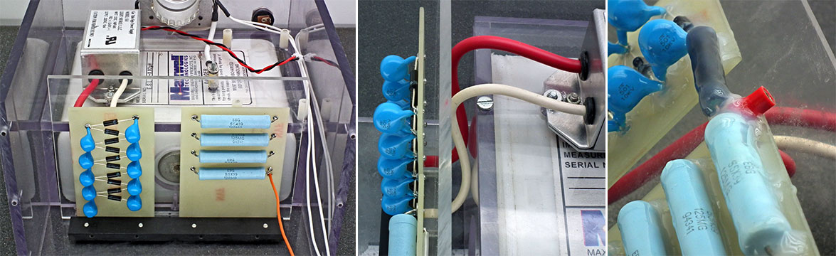
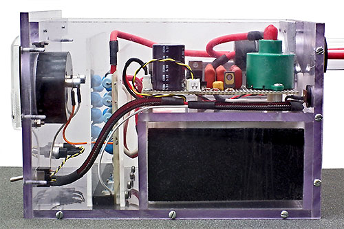
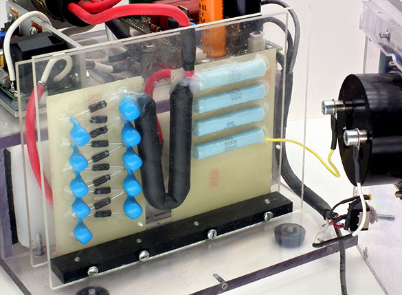
The voltage multiplier components & meter HV resistors were assembled using small metal rivets press fitted into holes drilled in unclad FR4 PC board. The boards
were mounted using #4-40 screws through a 1/8" thick acrylic sheet, a 1/2" wide spacer strip of 1/8" acrylic, the circuit boards and threaded into a 1/2" thick acrylic strip attached to the enclosure bottom. The acrylic sheet and a second sheet attached to the front edge of the
acrylic strip were used to prevent unwanted arcing from the HV components to items installed over the HV capacitor and on the front panel. The second image shows wiring from the HV inverter through holes in the rear acrylic sheet to the multiplier. The third image shows the second
HV capacitor charging resistor that was used between the multiplier board and HV capacitor feed point on the resistor board, the pin jack for the mating plug on the flash HV lead to make lead removal easy when needing to work on the flash tube and the silicon sealant used to coat
the HV components and connections to prevent corona & ionized air problems after the first HV capacitor charging resistor was destroyed by a spectacular arc over 3" long from the resistor up over the acrylic barrier to the ungrounded meter terminal which also destroyed the meter
of course.
|
|
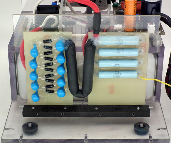
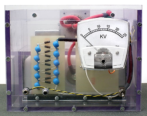
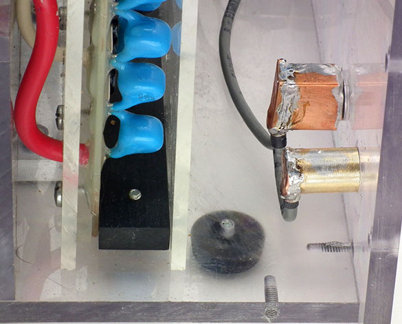
Above - final version of the voltage multiplier and meter resistor board assembly
after installing resistor #3 (which is 2 resistors
in series)
|
The meter was left it's pointer resting at 1/3 scale rather than zero, it's sensitivity no longer 50 µA and it's bright copper coloured hair springs dull black and sagging from being heated likely bright red for an instant. I
didn't have another 50 µA meter of the same style to use and wasn't able to find one to buy or want to make a new front panel for a different style meter, but luckily the meter coil was ok and the meter still worked somewhat so, with nothing to loose,
I tried repairing it. I've only made things worse when trying this in the past, but this time, after hours of fiddling with the hair spring coils I managed to finally get the meter to read correctly again. Meter readings had begun fluctuating and randomly jumping 1-5KV higher a
few minutes before the meter was zapped and I could have saved the meter and myself a lot of work if I was smarter and had figured out quicker this was due to ionized air building up and creating a path from the HV area to the meter for an arc.
I knew the second charging resistor was likely too low of a resistance and voltage rating and likely a bad idea to try, but it was the only one I had that I figured may work, would take 3 weeks to order and get one I knew would work and Tony and I were anxious to see the flash
work. When the flash was powered up and triggered it wasn't all bad news. The silicon sealant proved to have solved the corona and ionized air problem and the flash tube worked perfectly when the flash was triggered, but using too low of a resistance destroyed the HV inverter's
transistor.
There was not enough space between the two HV boards for one horizontal resistor with high enough voltage rating so 2 resistors in series were ordered and installed vertically as seen in the photos. Rather than coat the resistors with silicon sealant
like before, heat shrink tubing was easier to use this time. If I were to do it again however, I would simply use one circuit board for everything and pot everything into one solid block with threaded inserts to make mounting easy. This would also save needing the 1/8" acrylic
barriers.
|
|
Above - same as previous image, but with front acrylic sheet also in place.
|
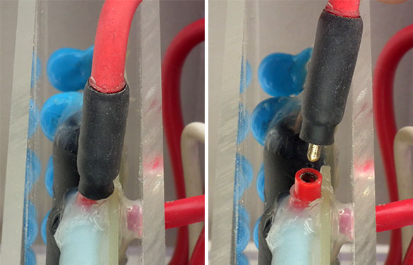
Above - A miniature HV connector was made by placing heat shrink tubing over the plug & HV wire while plugged into the socket and the tubing overlapped the
socket. When unplugged, silicon grease was applied to the jack and inside surface of the over lapping heat shrink to eliminate the chance of corona.
|
|
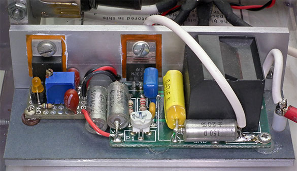
Above - final version of the trigger circuit board.
|
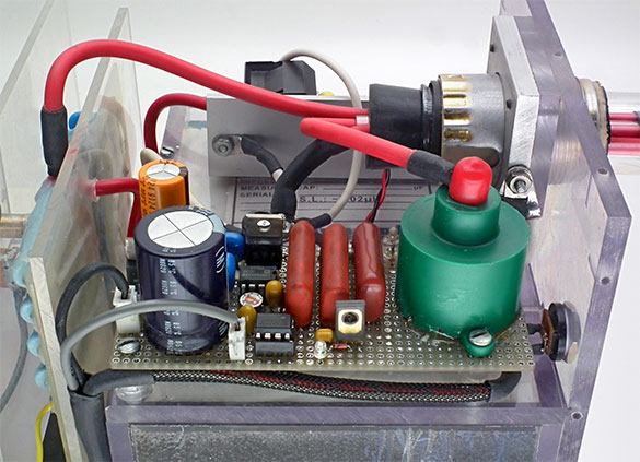
Above - final version of the HV inverter with it's voltage regulator installed to the left.
|
|
The small HV inverter in an aluminum enclosure isn't a bad deal, but required a few mod's. The capacitor in series with the transformer secondary was removed to increase the voltage the inverter can charge the HV capacitor to at any particular DC input
voltage to save having to buy a different wall wort with a higher output voltage than the one sold for use with the inverter that I had. I had also hoped this would allow the flash to be powered from as little as 12VDC, but voltage losses due to using a voltage regulator to adjust
the HV capacitor voltage prevented this. Something else about simply using a voltage regulator to adjust the HV cap. voltage was discovered when the flash was left powered on much longer than usual which is the HV capacitor voltage will slowly drop as the inverter transistor becomes
warmer. It's not a serious problem as the flash will likely seldom be left on longer than a few minutes plus the voltage only drops a few KV before the temperature levels off and voltage stabilizes around ≈23KV. When I get a chance however, I plan to change
how the HV capacitor voltage is adjusted that will eliminate the voltage regulator and also make the voltage temperature stable.
When the inverter was in its enclosure with supply voltage leads ≈10" long it appears the lead inductance somehow created a large voltage transient or oscillation each time the HV cap. was discharged that would often take out the inverter transistor. This
lead to replacing a small .047 mfd capacitor across the inverter supply voltage with a larger value 47 mfd tantalum capacitor. It also lead to removing the inverter from its enclosure and mounting as shown as removing the inverter from its enclosure to
replace the transistor each time was made difficult and became a real pain with how the enclosure is made and the inverter fits inside. It likely wasn't required, but two more 47 mfd tantalum capacitors were installed across the inverter supply voltage after the inverter
was installed on the aluminum channel.
The values of several other HV inverter components were also changed for various reasons and details about everything done are provided on the Inverter Schematic.
Right - A number of things were tried to get the triggering circuit to operate properly. The first circuit tried worked perfectly with just the triggering circuit board powered up, but was repeatedly triggered by noise as soon as the HV inverter was powered on. Things worked
fine again when the wiring to the front panel trigger input jack and manual trigger push button was disconnected indicating the problem was capacitive coupled noise from the voltage multiplier string. Replacing the twisted pair wiring with a shielded pair and shielding the push
button and jack as seen (right) did nothing to help with such an extreme electric field close by due to the high voltage involved. When it became obvious that the simple 2 transistor triggering circuit being used could never be made to work with such a high noise level a different
circuit tolerant to much more noise was tried that worked fine. The new circuit may not require the shielded wiring and other shielding added for the first circuit, but after seeing the voltage level of the noise without the shielding wouldn't be surprised it does and would take
the time to shield things well if I were to build another flash.
|
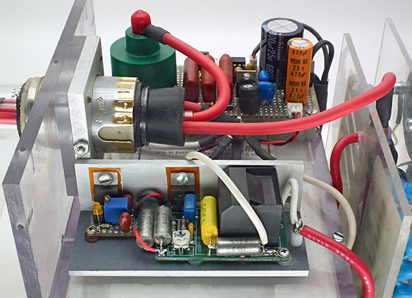
HV inverter & voltage reg. were installed on a L shaped piece of aluminum channel.
|
 |
|

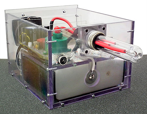
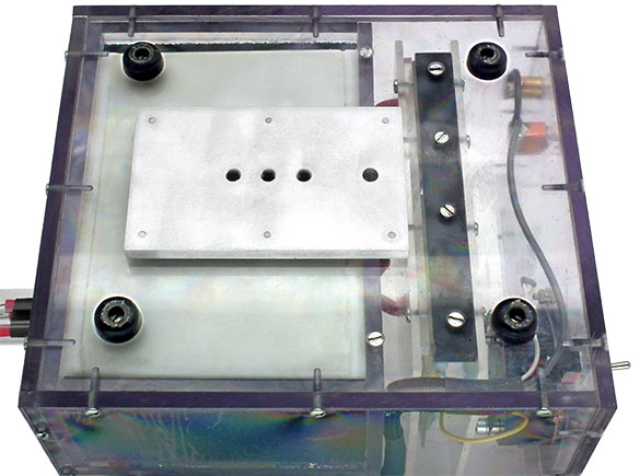
Top View of the completed unit.
|
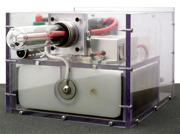
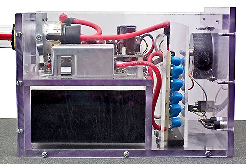
Rear View of the completed unit.
|
|
Bottom View of completed unit.
|
Left - A piece of 1/4" thick aluminum with 3 threaded holes for attaching the flash to a tripod was installed on the bottom of the flash with the center hole located at the point of balance. The 4th hole further right provides access to the center screw through the bottom into
the piece on the other side that boxes the HV capacitor in.
4 feet slightly over 1/4" high were also installed on the bottom to provide clearance for the 1/4" aluminum piece when the flash is placed on a flat surface.
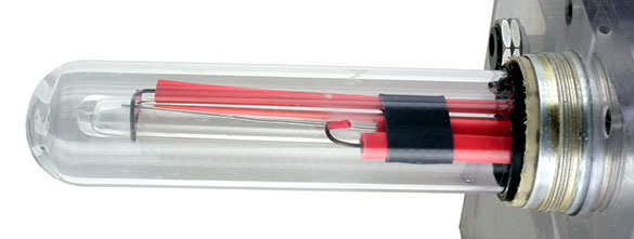
Above - Close up of flash tube with the Spark Gap set to 1.3"
|
|
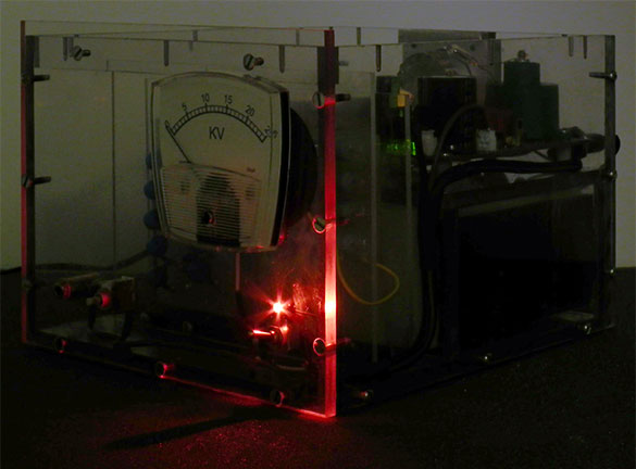
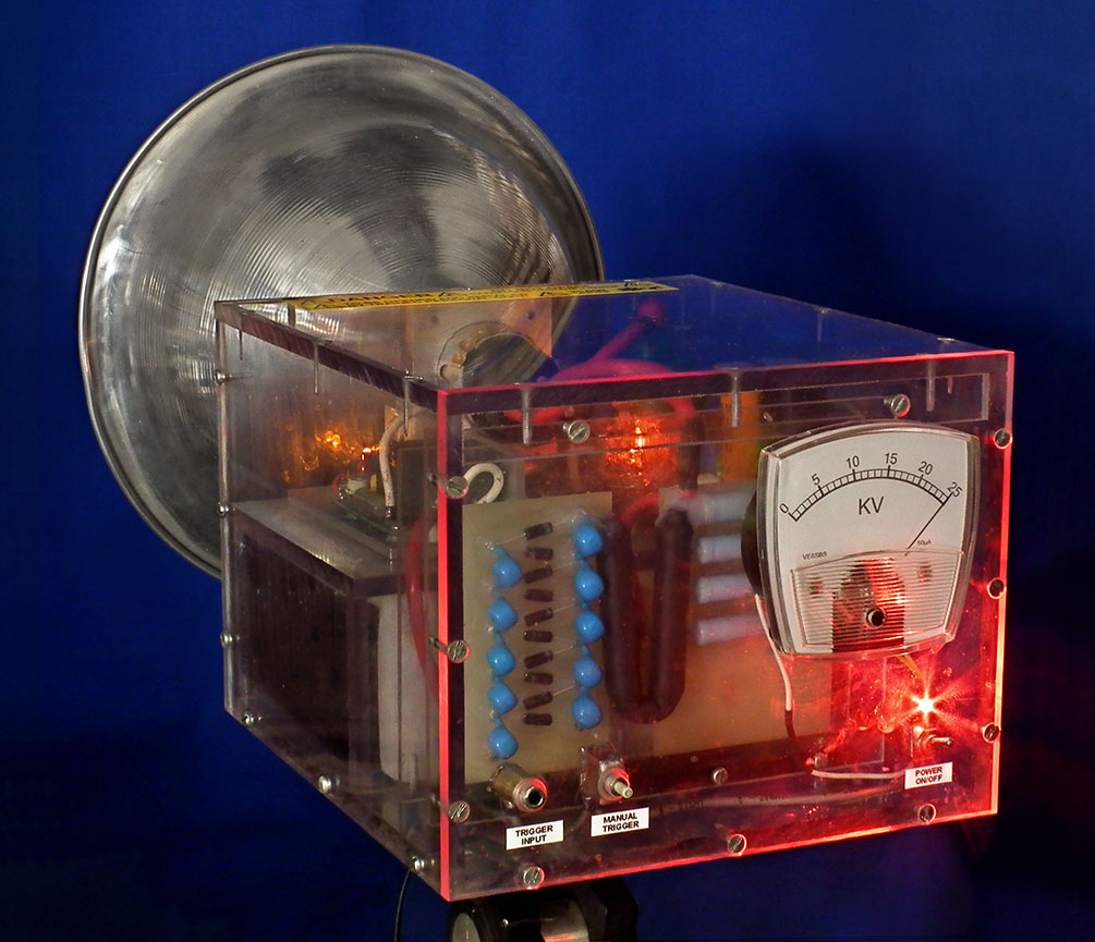
A small 3mm red LED power-on indicator was installed in a 3mm hole drilled part way into the back side of the front panel to have the panel distribute the light and allow the manual trigger push button to be located when needing to do so in a dark room as well as to provide
a neat lighting effect and more colorful and interesting photo of the flash for use at the top of this page.
Three other 3mm LEDs were also used, a orange LED to confirm the HV inverter is being powered, a green LED to confirm the trigger circuit voltage regulator is ok and a yellow LED that flashes each time the flash is triggered to confirm the triggering circuit is operating correctly.
These LED's aren't actually needed now that the flash is working properly, but were extremely useful while tracking down problems (as well as making the flash more colorful and interesting like the power on LED of course).
A neon lamp indicator was also used that was installed on the trigger circuit board to confirm the board's inverter is ok and the trigger voltage is between 300-350 VDC.
Flash Schematic.pdf
HV Inverter Schematic.pdf
Trigger Board Layout.pdf
|
|
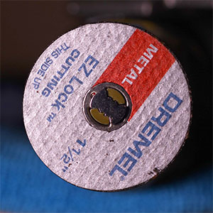 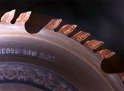
Tony has had his flash for a week now and has been trying to find something
too fast to photograph without any luck.Left are images of a dremel cutting disk turning 35,000 RPM and teeth on a 10" saw blade turning 3500 RPM that he took.
|
|

Left - This is the light pattern produced without a diffuser. The shadow seen around the 9-10 o'clock position is due to the HV ground lead that
runs the length of the flash tube. The shadow and overly bright center ended up not being a big problem however and the pattern was later evened out nicely using some non-gaussian
diffuser material from an old LCD monitor.
If I were to build another flash however, I would seriously consider trying a rectangular reflector with electrodes mounted beside each other (rather than one in front of the other) to eliminate the shadow problem.
That's all for now. Hopefully this has given those planning to build such a flash a few useful ideas and those simply interested in reading about them enjoyed reading about, and seeing images of the flash I built.
(Photography has been another hobby of mine since childhood and at one time my basement workshop was a darkroom equipped for color with a Super er Chromega 4x5 Enlarger. I've done some high speed photography using regular photo-flash units in the past and after building this
flash for a friend now find myself with the problem of wanting to do more and having to build another spark-gap flash for myself.)
|

 This project involves a number of potential
serious hazards and no one should even think about undertaking such a project unless they are aware of, understand and know how to deal with them, especially about the high voltage danger and with how to safely work with voltages up to the tens of kilovolts that can arc across
several cm's of air and require well planned insulation with proper materials. (Note: Some materials usually considered non-conductive and commonly found used for insulation at lower voltages become conductive and unsuitable for HV insulation starting as low as a thousand volts.)
This project involves a number of potential
serious hazards and no one should even think about undertaking such a project unless they are aware of, understand and know how to deal with them, especially about the high voltage danger and with how to safely work with voltages up to the tens of kilovolts that can arc across
several cm's of air and require well planned insulation with proper materials. (Note: Some materials usually considered non-conductive and commonly found used for insulation at lower voltages become conductive and unsuitable for HV insulation starting as low as a thousand volts.)