BEAR 1 & 2 Temperature Sensors
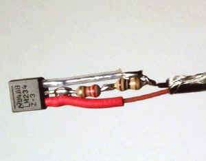 |
A LM234 adjustable current source IC is used as a 1 uA / degree Kelvin temperature sensor. The 1 uA/°K calibration was done by hand by selecting two 1/10 watt 5% resistors that in series result in a current of 1 uA/°K from the LM234 (that by calculation should be 227 ohms) and is more accurate than using the closest value single 1% resistor. The probe is connected to the remaining circuitry with a miniature 2 conductor shielded cable. |
|
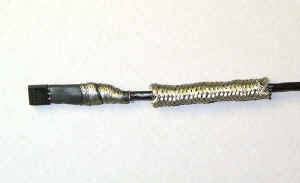 |
This photo shows the interconnecting cable shield partially wrapped over the probe assembly that has been enclosed within a piece of heat-shrink tubing. A piece of shielding braid, obtained from a scrape of small coax, is positioned and ready to be slipped over the probe. |
|
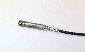 |
Here the shielding braid has been slipped over the assembly. | |
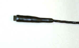 |
The shielded probe was encapsulated in a piece of heat-shrink tubing with an inner wall that melts and seals the assembly. | |
| The 1 uA / degree Kelvin current from each sensor is converted to 19.6 mV / deg K. This voltage is level shifted −2.5 volts to keep the resulting voltage, over the −90°C to +100°C measurement range, within the 0 to +5 volt input range of the MIM. Making each °K = 19.6 mV (the MIM's A/D 1 bit resolution) means each 1°C change of measured temperature will result in a change of the telemetry temperature A/D value also by 1. Thus, rather than having to use the formula (( A/D Value x .0196) - 2.89) / .0196 to calculate the measured temperature, one can simply remember that 0°C is equal to the telemetry value of 147 and subtract 147 from the current telemetry value to find the temperature. Update: It is hard to shield against RFI when working within inches of a 5 watt transmitter. Probe shielding did help some, but it is not the total solution. On the next BEAR mission I am going to try using the Dallas digital temperature sensors to overcome RFI problems. |
||
| To BEAR Home Page |