RTrak-HAB V1.9 TrackerPrototype RTrak-High Altitude Balloon Tracker from RPC Electronics) This page is a continuation of the RTrak-HAB V1.5 page. V1.5 was a prototype and V1.9 is the version that will soon be available now that MX-146LV transmitter modules are available again. V1.9 incorporates all the changes shown on the v1.5 page as well as better LDO (low drop out) voltage regulators and a few new features. At least that's what I wrote on Jan 28th when the V1.9 board was received and I thought this page would be finished after a few quick tests and sales would begin in a few days. But the voltage regulators had been changed to the ultra LDO ones I mentioned wanting to try on the V1.5 page and testing quickly revealed a problem, that ultra LDO reg's are not as simple to use as regular ones and another board revision was required to make things 100%. Having to revise the board will delay things a bit longer, but the regulator problem isn't all bad news as it lead to finding even better regulators to use. And since little will change on the next version, other then the regulators, I'm going to simply continue describing the V1.9 board to save everyone having to wait any longer for the changes made since V1.5. |
|
|
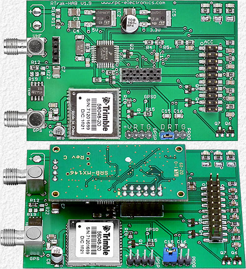 |
Left - the V1.9 board without a MX146-LV transmitter module installed (top) and with a transmitter (bottom). Size: 2.08" x 3.2" x .67" high Input voltage is via 2 solder pads like v1.5, but the reverse voltage protection diode was removed to make the minimum input voltage as small as possible. The voltage regulators were also changed to the ultra LDO ones I mentioned wanting to try on the V1.5 page which made the Maximum Input Voltage = 20V, the Minimum Input Voltage = 5.3V, and allowed the tracker to continue transmitting its location down to 4.3V. But the regulators on the next version will even be better and also provide Note: Analog telemetry data is not correct when input voltage is < 5.2V as the 5V reg. is unable to supply the 5.0V A/D converter reference voltage required. |
|
|
With an active GPS antenna the Operating Current at 6 VDC is 85-90 ma. (Idle) and ≈ 310 ma. (transmitting) V1.5 had dual color LEDs to monitor tracker operation, but V1.9 has 3 individual LEDs (upper-right in photo) with solder jumpers that can be removed to disable the LEDs and save a few ma. I personally see no need for a Power On LED with 1 of the others blinking every second (although it does look pretty) and disabling it saves 12 ma.
The temperature error of an un-calibrated LM335 sensor is typically 1°C, but it can be up to 3°C so pads for 2 additional resistors (R19 & R22) have also been provided for those that wish to spend the time to trim the sensor output for more accurate readings as described in LM335 data sheets. The V1.5 page also shows adding resistors from 5V to several of the ACC connector analog inputs for additional temperature sensors, but a resistor is now provided on each input along with a 0.1 mfd capacitor to ground to reduce any RFI that remote sensor leads may pick up. The resistors are all 3.3K for additional LM335 temperature sensors as this is what most will likely want to add at least a few of, but they are easy to change or remove for sensors that require a different value or no resistor. Anyway, the important thing about all of this isn't the value of the resistor provided, but that there's now a place provided for one, when one is required. And the V1.5 12 pin ACC connector is now a 20 pin connector to accommodate 4 new digital output signals. One output is a transistor switch from +5V to provide the 5V signal required to have any number of CHDK cameras simultaneously capture sets of images at programmed intervals synchronized to tracker transmissions to allow panoramic images to be made from each set of images and to save countless time trying to figure out exactly when, where and at what altitude each set was taken. The other 3 outputs are a FET switch to ground for such things as cutting away from balloon at a programmed time (in case one has a floater), cutting away from balloon fragments after a balloon bursts (to save having a tangled mess), delaying parachute deployment until a programmed altitude (for a quicker descent to reduce recovery distance) and whatever else one may want a programmable output for. Firmware to support the new outputs is not yet written so they will not be immediately usable, but updates will be free when it's available and updating RTrak firmware is very simple. March 23, 2011 - Revised boards have been shipped to Jason and assembled trackers should be available soon. More info and photos of the final board will follow on a new RTrak-HAB V1.10 page as soon as one is received. |
||
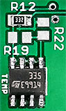 I showed adding a temperature sensor on the V1.5 page to provide the temperature that's reported in the APRS comment field with the battery voltage, but V1.9 now includes an on-board LM335 sensor.
| To BEAR Home Page |