|
Dual-Band Center-Fed Folded Dipole
Antenna for High Altitude Balloon Use
May - 2000
|
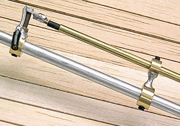 |
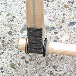
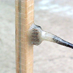
A lot of time was spent researching, learning about & building antennas to find the most suitable one to use for BEAR-1, but without something like the Bird antenna analyzer I was able to borrow it would have been impossible, or at least taken an impossible amount of time, to successfully
build any. This photo shows the gamma match on one of the numerous antennas of different types I built & tested. The dipole is 3/16" dia. aluminum rod, but, except for the folded half-wave dipole antennas I ended up using, this and every other type of antenna and method to match them to 50 ohm feed line all required difficult
adjustment and were sensitive to nearby objects.
|
 |
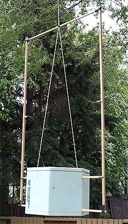
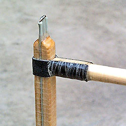
The decision to build & use 1/2 wave folded dipole antennas was easy after finding they were the least affected by nearby objects, required no tuning other then having to be made the correct length, one of the easiest to build, adjust, make light weight plus, being dual-band, good for cross-band repeater use. I simply used
300 ohm TV twin-lead feed-line placed between (2) 3/16" x 3/8" balsa wood strips to keep it laying flat and then spiral wrapped the sandwich with thread to keep everything straight and in place while wrapping 2 layers of 0.6 oz fibreglass cloth around the assembly and applying epoxy resin to hold it all together, protect and
hopefully provide enough strength for the antenna to survive whatever landings may bring.
|
 |
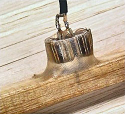
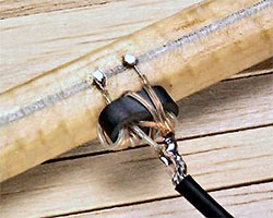
A 4:1 balun from a TV mini-match worked perfect to match the 50 ohm coax feed line to the 200 ohm antenna. 5 minute epoxy glue was used to attach the balun and then more was applied, in workable amounts, until the balun and all of the fragile wiring was completely embedded in epoxy. |
 |
To further protect the balun, wiring and provide better strain relief for the feed line, several layers of fibreglass cloth and epoxy were then applied over the embedded balun and wiring. |
 |
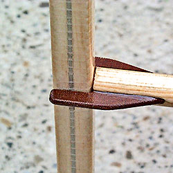
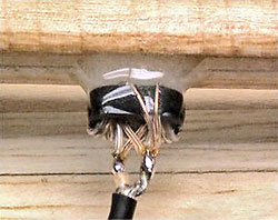
The length of the folded dipole was calculated using the standard formula and after soldering the two twin-lead conductors together, at what will become the bottom end, one of the conductors was cut at the measured half way point for the balun connection. The upper half end of the twin-lead was cut and joined about 1/2" further
from the center then calculated however, to allow tuning the antenna by slowly trimming the upper end shorter while checking for the best possible match. The velocity factor of different twin-lead feed lines varies plus the balsa wood and amount of epoxy used affects the VF so expect to make and perhaps have to toss several
antennas before finding the exact length of dipole needed for the best match in your particular case.
|
|
|