|
A VHF 1/2-Wave Center-Fed Dipole Antenna |
|
||||||||
|
|||||||||
|
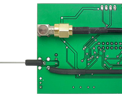
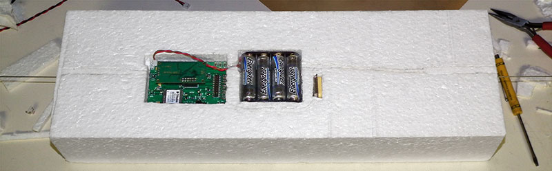
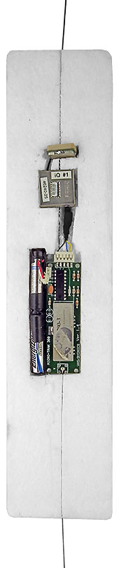
We've been using RTrak-HAB trackers and following is how I've been using them to make back-up trackers, but the same could be done with most any tracker hardware. A 1/2-Wave Center-Fed Dipole Antenna is used, much like the inline element ones shown on the 1/2-Wave Center-Fed Dipole Antenna page, but in this case the VHF antenna SMA connector on the tracker is removed and the antenna elements are simply soldered directly to the tracker PCB where the VHF antenna connector had been as shown below. Several layers of heat shrink tubing are also used over the elements where they cross over the board to ensure they'll never be able to short to the board. |
|||||||||
  |
|||||||||
|
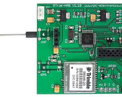
The SMA GPS Antenna connector is also removed from the top side of the tracker PCB, turned 180° to face in the opposite direction and then re-installed on the bottom side of the board. |
|||||||||
 |
|||||||||
 |
|||||||||
|
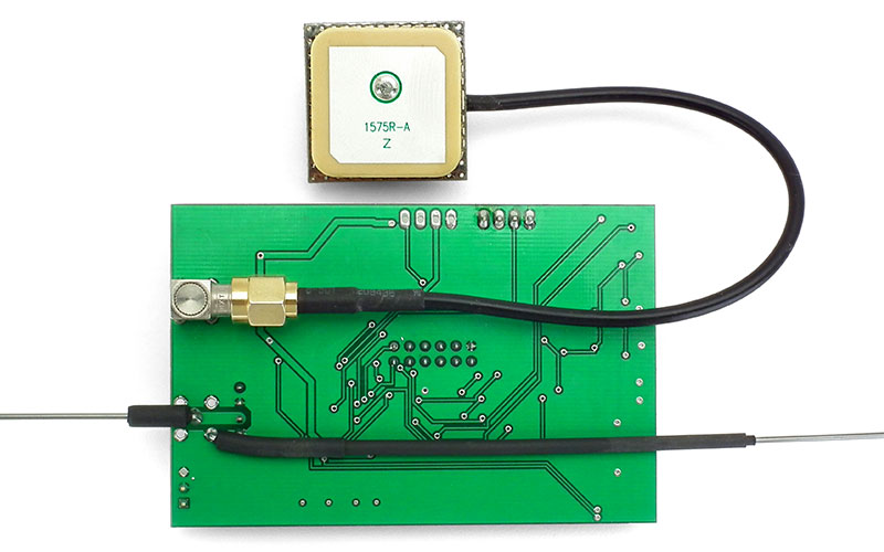
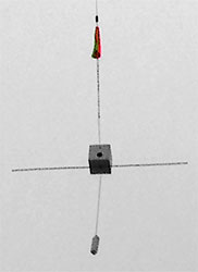
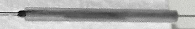
In use the antenna elements are positioned vertically with the active element below the ground element. Eye protection (as described on the previous page) is provided at the tip of the lower active element,
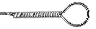
but at the tip of the upper ground element a loop is formed that's used to tie the lift line from our payload box to. When making the upper ground element you need to start with a length of music wire |
|||||||||
|
|||||||||
|
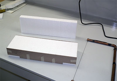
Below is our first
Below is the cone
|
|||||||||
|
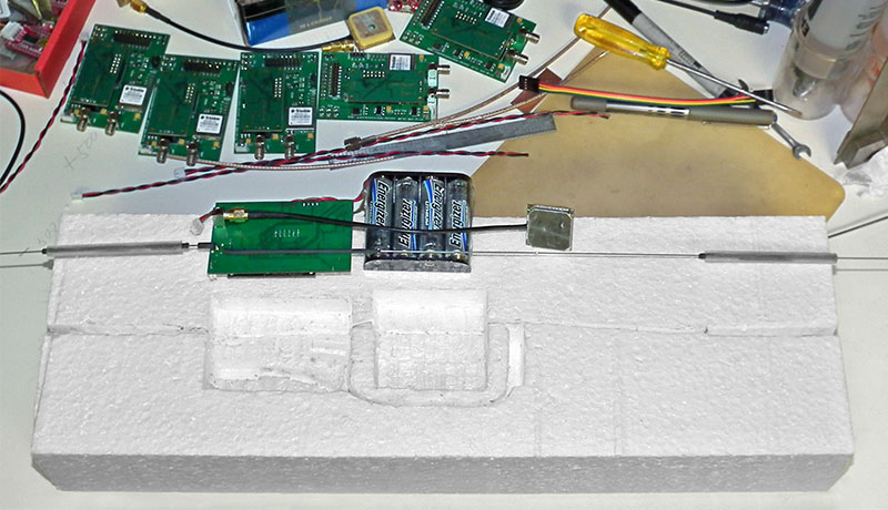
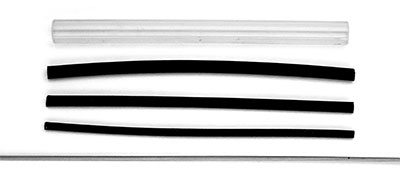
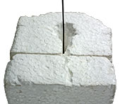
After placing the 1/4" tubing sections on the elements, the 90° bend in each element where it will be soldered to the PC board can be made at the point that will make the length, from where the active element will be soldered to each tip, 19-5/8". Once bent, the excess length after leaving what's needed for soldering each element to the PCB, can be cut off. Below is a tracker ready to be installed in it's foam enclosure and, below that, is the completed tracker ready to have the upper half of it's enclosure placed on top, the two halves taped together and the tracker used for a flight. |
|||||||||
 |
|||||||||
 |
|||||||||
|
I wouldn't suggest also making and using a loop at the end of the bottom active element to tie on additional items as the soldered PC board connection would likely fail and you would lose what was tied on as well as the tracker signal. We have sometimes used 2 of our back-up trackers on a flight with one as the primary tracker between the parachute and payload and one as the back-up tracker tied on below the payload, but we use one continuous length of lift line from the parachute to the payload with the primary tracker simply connected to the line by tying the line through and to the trackers upper element loop and adding a few wraps of tape around the line and lower antenna element to simply keep everything in-line. |
|||||||||
 several
inch's longer than for the active element and make the loop far enough from the end to leave a straight section ≈ 1-½" long after the loop so the loop can be soldered closed as shown. Solder alone isn't very strong plus one needs a way to keep the loop tightly closed while it's being soldered
so it's tightly wrapped with a length of bare wire-wrap wire first for a very strong easy to solder joint.
several
inch's longer than for the active element and make the loop far enough from the end to leave a straight section ≈ 1-½" long after the loop so the loop can be soldered closed as shown. Solder alone isn't very strong plus one needs a way to keep the loop tightly closed while it's being soldered
so it's tightly wrapped with a length of bare wire-wrap wire first for a very strong easy to solder joint.
| To BEAR Home Page |